Reusing PCB Design Elements
Categories:
Board template layout
Here’s the scenario: you’ve come up with a great product design, designed the electronics, written the software, set up testing, designed an enclosure, set up manufacturing, and are shipping products. Version 0.1.0 is out the door in the hands of happy customers. You followed good project management steps but had to keep to a tight schedule so there are valuable features you want to add. So you start working on version 0.2.0 (semantic versioning).
The end goal is to release a more useful product while minimizing both development time and total cost, especially opportunity cost. To do that, we plan on using the same mechanical design and reusing as much work as possible. The updated electronics will need to have a compatible mechanical form and to match the existing system interfaces.
Consider HP oscilloscopes as a case study; over time their designs evolve through gradual updates. The power supplies, interface, display driver, computer module, and analog electronics are typically on different boards. These boards are then updated separately with many carried over to the next design. The designers only need to change the section that will add value. This kind of hardware modularity mirrors good software design. It simplifies maintenance, improves testability, and reduces risk when making changes.
We refer to the design step of highlighting sections that can be broken out as factoring or decomposition (same process as with software architecture or grade 7 math). Factoring designs into different boards maximizes reuse as well as simplifying board manufacturing and test.
Factoring does not have to stop at the system level; factoring at the PCB level can also be done to great effect. This is typically more important for a small team or a single designer to maximize their time. You can factor the board design itself, allowing easier reuse of sections that are known to be good. This is not exactly a new concept but there seems to be little discussion of intelligent work flows. Here I explore and expand a workflow that we’ve been using at EOI & HEO for several years, to great effect.
KiCad uses hierarchical schematics only. There are no global pages as in other EDA packages (Embedded Computing: KiCad Hierarchical Sheets for Enhanced Schematics). Provided these hierarchies are well designed they can easily be copied to new designs for reuse.
Reusing sections of a design raises a few problems. Not least of these is maintaining a master version and updating the shared design over several derivative works. Templates are a useful abstraction to work with; KiCad and Altium both have design templates as built-in features. Having the feature in your tool of choice isn’t required (I prefer avoiding them). KiCad’s technique copies the entire template directory into your new project with no update facility. This could be a problem: the design is out in the world and not tied back to the master version at all. What we want is ways to make updates and maintenance as simple as possible. To do this we will need tooling and/or workflow.
Sections that can be reused
- Parts & Symbol Libraries: These are commonly reused and shared. Make sure yours are version-controlled and the library version (or commit) is noted in the design to help track errors and changes.
- Schematic Templates: version-controlled template, preferably submoduled in the design.
- Reused schematics: version-controlled and submoduled. The schematic should be referenced in its location with the submodule (i.e. “../power-supply-a123/buck-smps.sch”)
- The template must be version-controlled. Sections that are unchanged can then be easily and reliably updated. I prefer to submodule a git repo and copy the files that will be edited rather than use the template tool to keep the version control structure.
- Board outlines should be made a footprint to allow them to be updated. Updating the parts on the board will allow designs to be updated with minimal intervention.
- Critical component placement should be specified in a document and auto-checked with an auto-placement tool such as kicad-parts-placer. The designs can be checked for compliance with the specification automatically.
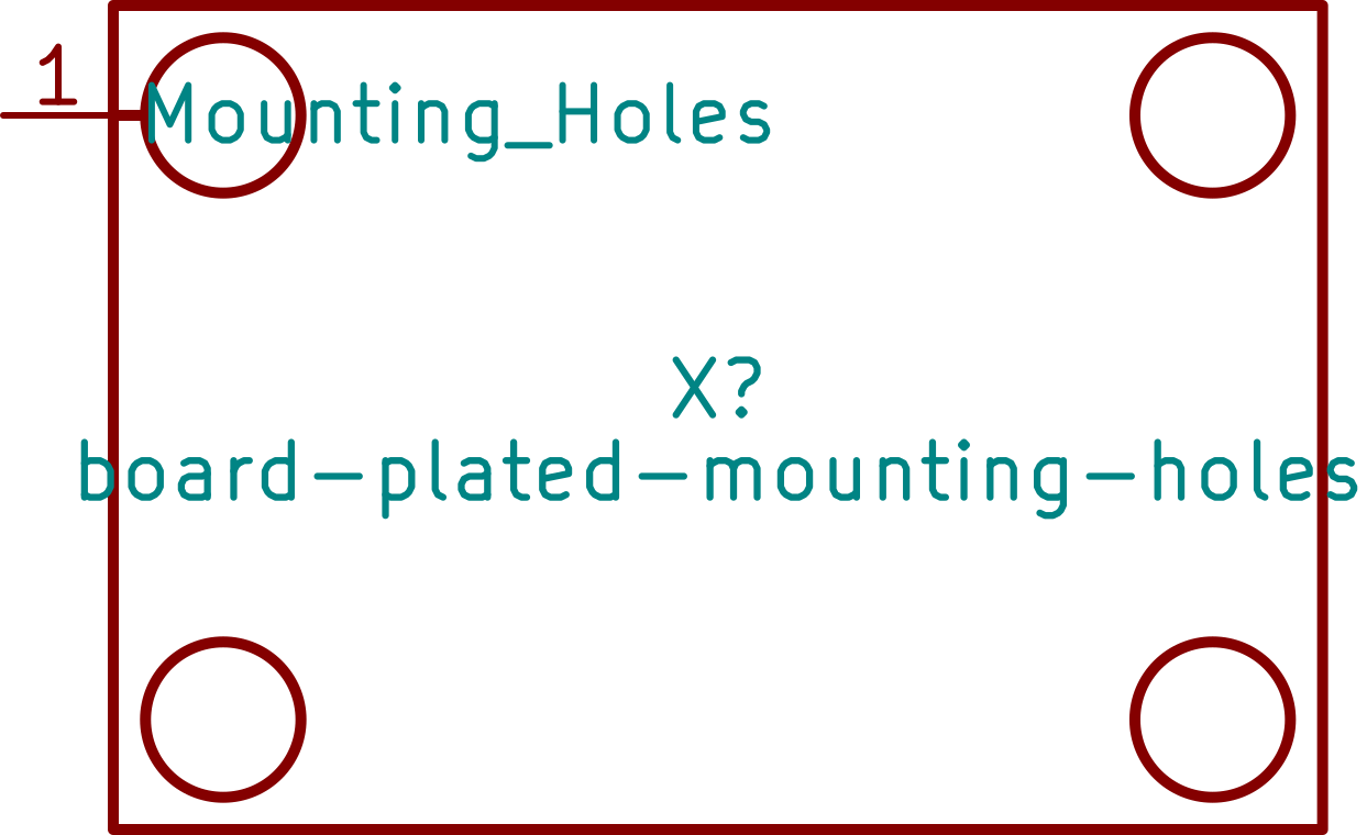
Standard grounded mounting hole board symbol
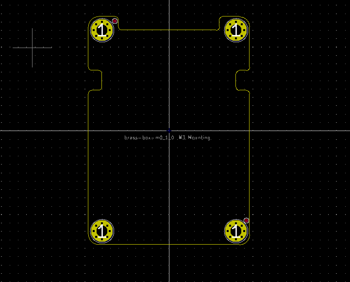
Example of a board footprint
Board template layout
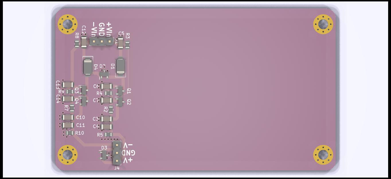
Render of template board with power supply layout
Updating Reused Sections
If all these steps are followed then the pain of updating derivative designs can be reduced.
- Update shared schematics: Update design in template repository, update all design subdirectories
- Update shared form-factor: Make footprint changes and update the board part.
- Update schematic template: These are cosmetic and not critical. I prefer to softlink the templates from a single repository in my home directory. Missing style templates are annoying but not critical. Subrepositories can always be used too.
- Update/Check part placement: Use kicad-parts-placer to check placement or export to centroid and confirm values are equal
- Update template layout: The template layout tool doesn’t have any update facility; once you make a design it is completely separate. This could be done using a pcbnew tool but none exists that I know of.
- Update derived schematics: A derived schematic starts as a template schematic but is altered for the specific design so are no longer updatable without design effort. To avoid needing to do updates by hand the shared components should be in a shared schematic and only pulled in as a hierarchical sheet.
Reuse
That brings us to reuse.
- Reuse schematic sections: If the design is significant enough that updates by hand are unattractive, it can be factored into a shared schematic. Simple sections can be added to a template schematic.
- Board outline & mechanics: Add the board as a footprint to a shared library. Use a common point on the board as the alignment & grid origin so part placement is easier to compare. I prefer to use the center of the board as the origin but this may need to be different depending on your design.
- Section Layout: Store the section as a PCB with its schematic as a template. If you’re only reusing a single layout block then you can import the template as the base PCB. If more than one section is being imported, the sections need to be copy-and-pasted into the design. In the general case the reference designators will need to be renumbered; a tool is needed to update both the PCB and the schematic reference designators. This would be improved if there was a scripting tool like pcbnew for schematics. This could be accomplished by compiling a library and using ctypes but does not yet exist. In the worst case scenario, the schematic reference designators can be updated by hand and the pcb reference designators updated with a script.
- Mechanical form factor: The form factor can be reused by hand by following a specification, or can be maintained with an auto-placement script. This will also help detect if parts were accidentally moved during layout or if the mechanical specification needs to be changed.
Conclusion
- Favor a master repository for a reused design over templates. This allows using submodules instead of only copying files which help keeps track of changes and ease updates.
- Design reuse can lead to an explosion of designs while preventing divergence of related designs.
- Some additional tooling is required before design section libraries can be reliably dropped onto a board
KiCad Templates
- KiCad Template Repo
- How to Create a Template
- VoltLog - Use Templates in KiCad 6 To Save Time
- John’s Basement - KiCad 5 #32 Project Templates
- EENow - KiCad System and User Templates
- Tech Explorations - Create a New KiCad Project From a Template
KiCad Template Example Projects
- https://github.com/AchimPieters/KiCad-Templates
- https://github.com/botanicfields/KiCad-Template-M5Stack-FDM
- https://github.com/neggles/kicad-project-templates
Altium Templates
- https://resources.altium.com/p/using-project-templates-pcb-design-development
- https://github.com/QWaveSystems/QWAVE_Raspberry-Pi-CM4-Altium-Library
- https://github.com/jairov4/mini-pcie-card-template
- https://github.com/dee3mon/altium-templates