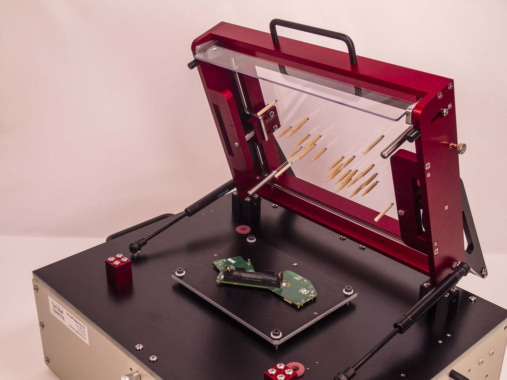
Building an Automated Test Jig: Hardware
Categories:
Part 2. of figuring out how to build a series of automated testing jigs for Hobbs ElectroOptics and ElectroOptical Innovations. The first part “Requirements and Resources” is available here. Like the first part this focuses on development and low scale manufacturing.
The most straight forward method for sourcing parts is looking at the kits available on the market. Some of the companies that offer kits are listed in “Requirements and Resources”. The parts can obviously purchased in those kits or similar parts can be acquired from suppliers like Digi-key or aliexpress.
Everything is called a pin or plate, be prepared for this.
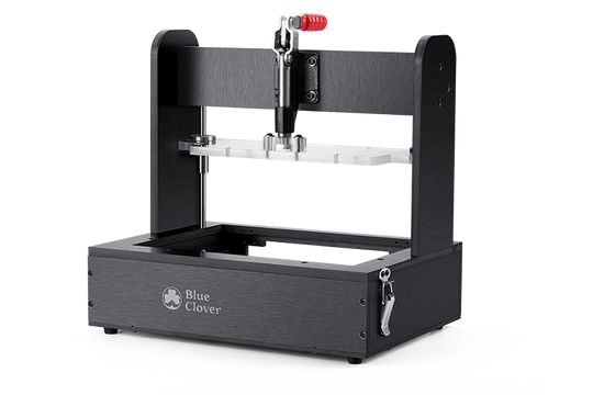
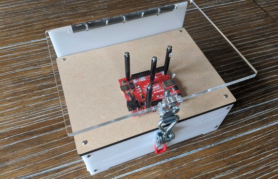
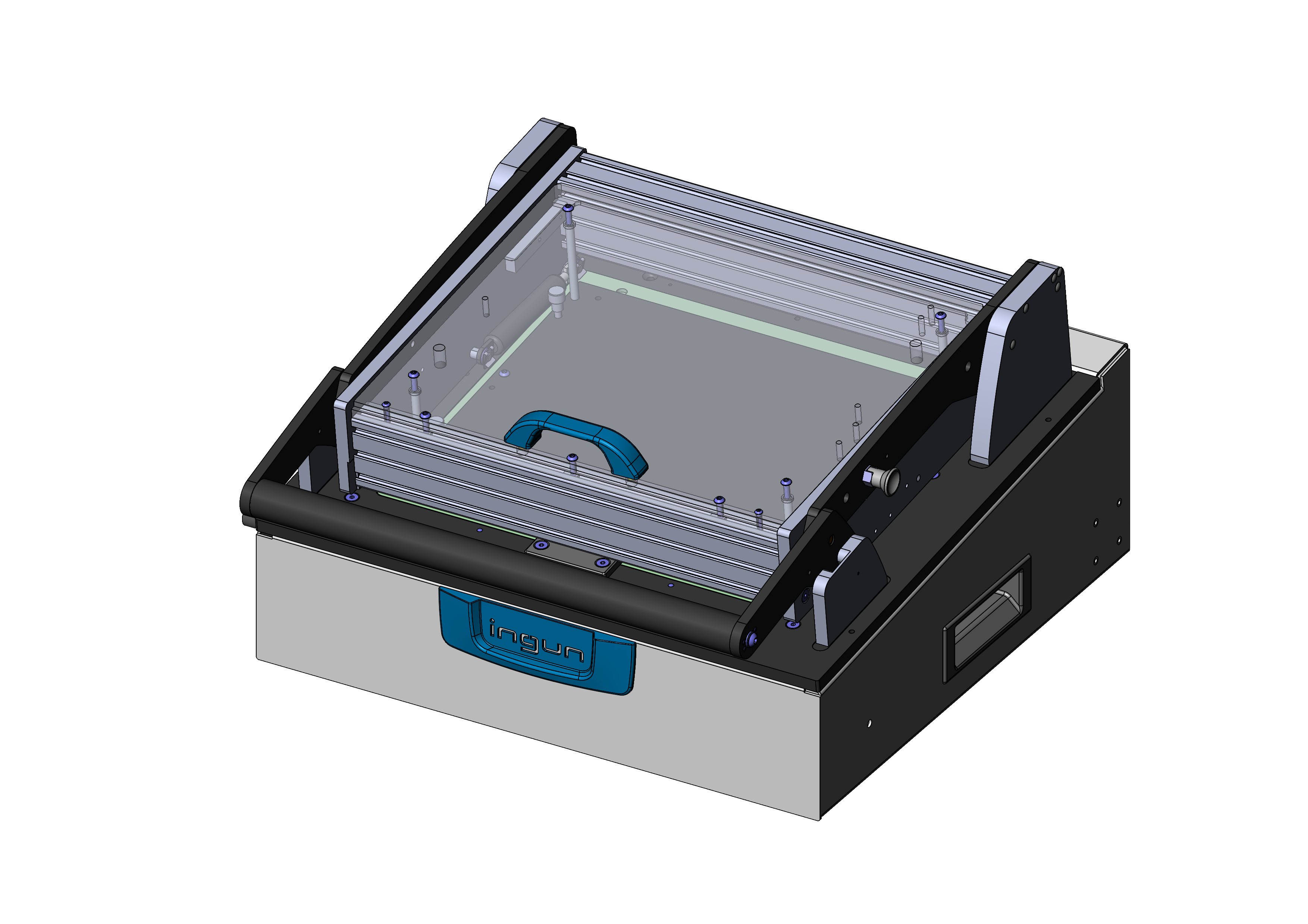
Fixture (AKA. Stand, Press, Clip, etc.)
This is the mechanical frame, several terms are common with ‘fixture’ being the most popular.
Probes
ATE Probes
 |
|---|
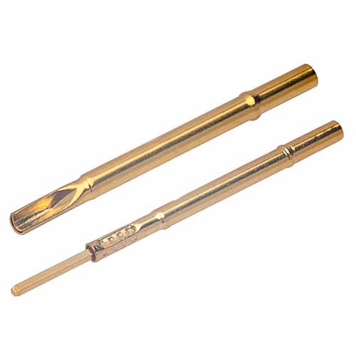
| ATE Socket |
 |
|---|
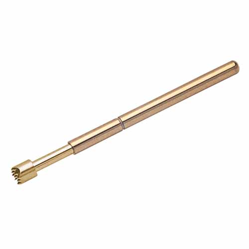
| ATE Crown Probe |
ATE probes are the standard connectors for this job. There are a variety of heads, lengths, diameters (called pitch), materials, sockets, attachment styles, etc. Most of the characteristics are standardized and can be purchased like fasteners from McMaster-Carr. The best guide I’ve found is Harwin’s.
- Harwin Test Probes
- Coda System Test Probes
- FixturFab: Choosing Probes
- Ingub Test Probes
- Hartman Test Probes
Apart from the traditional suppliers no name probes and sockets are available from many stores on aliexpress. The price is much lower but the quality may match.
- Sockets: https://www.aliexpress.us/item/3256803497397799.html
- Two Part Probes: https://www.aliexpress.us/item/2251832760194599.html
Pogo
Pogo pins consisting of a plunger (or head), barrel (or body), and a fully encapsulated fine spring, to provide the spring force required to maintain positive contact. All have a high durability, exceeding 10,000 mating cycles. Pogo pins are not typically used in commercial ATE test jigs.
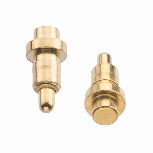
Through hole Pogos
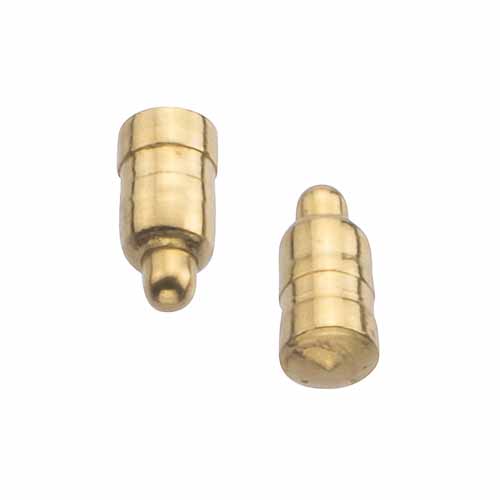
SMT Pogos
Pressure Pins
Pressure pins aim to distribute force evenly over the test unit. Typically these are mounted directly to the top plate. These pins are distributed as evenly around the board as possible, avoiding components whenever possible. These are typically nylon to avoid marking the board. These should be placed close to where the test pins are to minimize board bending.
Known as:
- Pressure Pins
- Pusher Finger
- Hold Down Posts / Rods
- Pressure Bar
- Push-rod
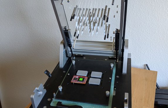 |
| FixturFab Ingun Production Fixture Example of separate tip pressure pins on the top plate. FixturFab uses 45mm ‘Pressure Pins’. Appears to be the same and Ingun |
 |
| Coda-Pin Pusher Finger Coda-Pin |
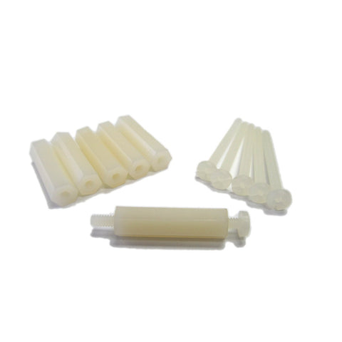 |
| Merifix ‘Hold Down Posts’ Merifix uses nylon screws and hex long nuts, referring to the assembly as ‘Hold Down Posts’! |
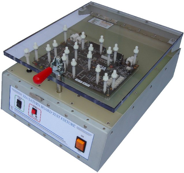 |
| Test Electronics ‘Press Rods’ Test Electronics use conically tipped nylon screws, referring to them as ‘Press Rods’. They appear to be identical to Coda-Pins. |
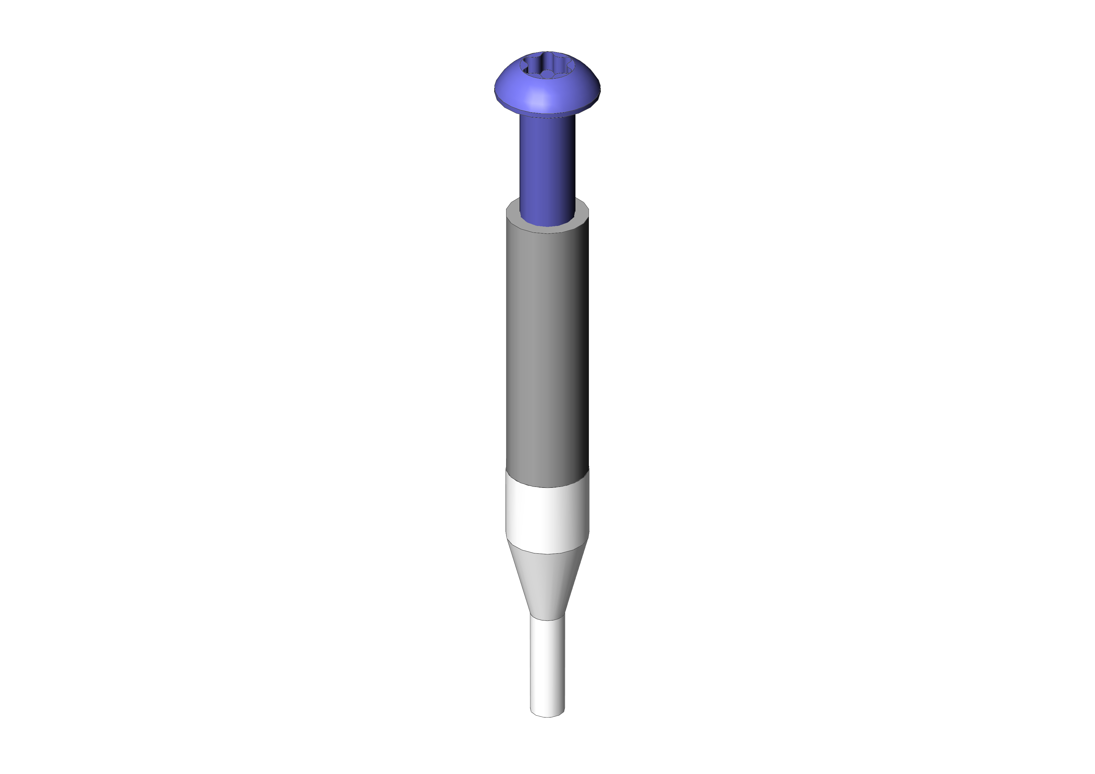 |
| Ingun ‘Push Rods’ Ingun’s nylon tipped pillars. The tips are replaceable and made of POM, this is significantly nicer than than nylon ones. |
Aliexpress Pressure Bar |
| Aliexpress Pressure Bar |
Guide Pins
Guide pins are spring loaded conical pins that help precisely locate the design. These sit proud of the test pins and should be evenly distributed, picking up the boards mounting holes. It is useful to ground these, ensuring ground is connected first. These are not strictly necessary and skipped in several designs. The XY alignment can be done with the outline of the board.

Aliexpress Guide Pins
- Ingun: Tooling Pin https://ingun.com/en-GB/FS-GF?order=topseller
- Merifix: Locating Probes https://store.merifix.com/collections/accessories/products/locating-probes
- Aliexpress: https://www.aliexpress.us/item/3256801915925566.html
Spring Loaded Support Pins

Spring Loaded Support Pins
Coda-Pin does not advertise using guide pins, preferring a spring loaded plate or support pins.

Coda-Pin Construction
- Coda-pin Floating Pins: https://coda-systems.co.uk/product-category/specialist-test-products/test-jig-parts/floating-pins/
- Ingun PCB Support Pin: https://ingun.com/en-GB/GKS-102-250-400-P-3002-W/GKS-102250400P3002W
- Aliexpress: https://www.aliexpress.us/item/3256803840038388.html
- On Aliexpress the part numbers used are GP-1* for 3.2mm tip diameter and GP-2* for 5mm. Various body lengths and travel distances are available.
Guide Plates
Some sort of alignment is added for XY placement. Ideally this allows the operator to roughly place the test unit with it falling into place. The outline should avoid misplacement if possible although many boards are symmetrical, the test unit should not be damaged if put in incorrectly.
Options for this are pins, plates, or a custom outline (laser cut, routed, 3D printed, etc.).
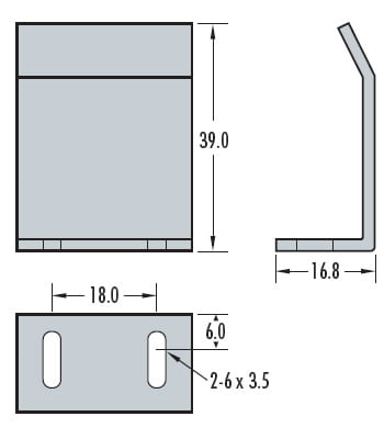
Coda-Pin Guide Plate
Taper pins can be used picking up be board outline, however they are not as adjustable as plates.
Pin Cassettes
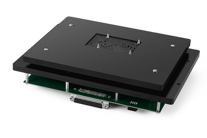
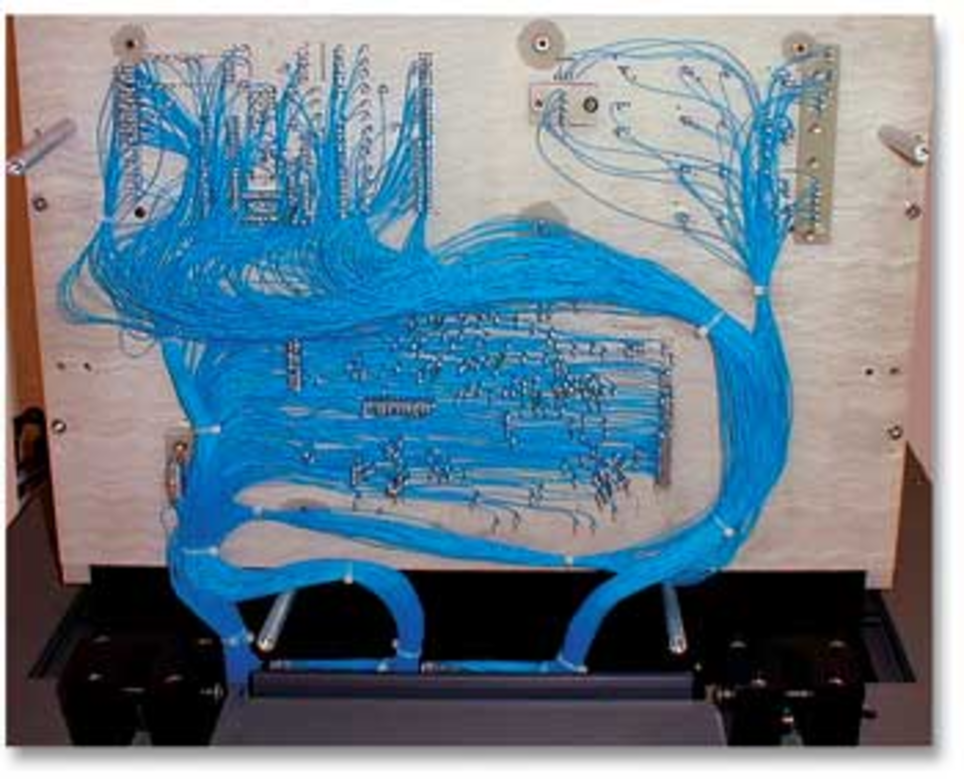
Pin cassettes are the entire pin assembly that goes into a test press. They contain the guide pins, test probes, guide plates, and connectors. Ideally these are interchangeable in a press like the Blue Clover cassettes. Traditionally wire wrap was used to connect probes leaving a rats nest of wires running under the unit.
Electronic Design ATE
With the cost of PCBs in this day and age I avoid hand-wiring to this degree.
Cassettes are much more common in production than development jigs. The development jigs usually act as an inseparable block.
