Sigrok + $10 Logic Analyzer
Sometimes, the simplest tools can save hours of frustration. When I found myself on the road, away from the lab, struggling to debug I2C and SPI issues, I turned to a surprisingly capable $10 fx2 logic analyzer, powered by Sigrok.
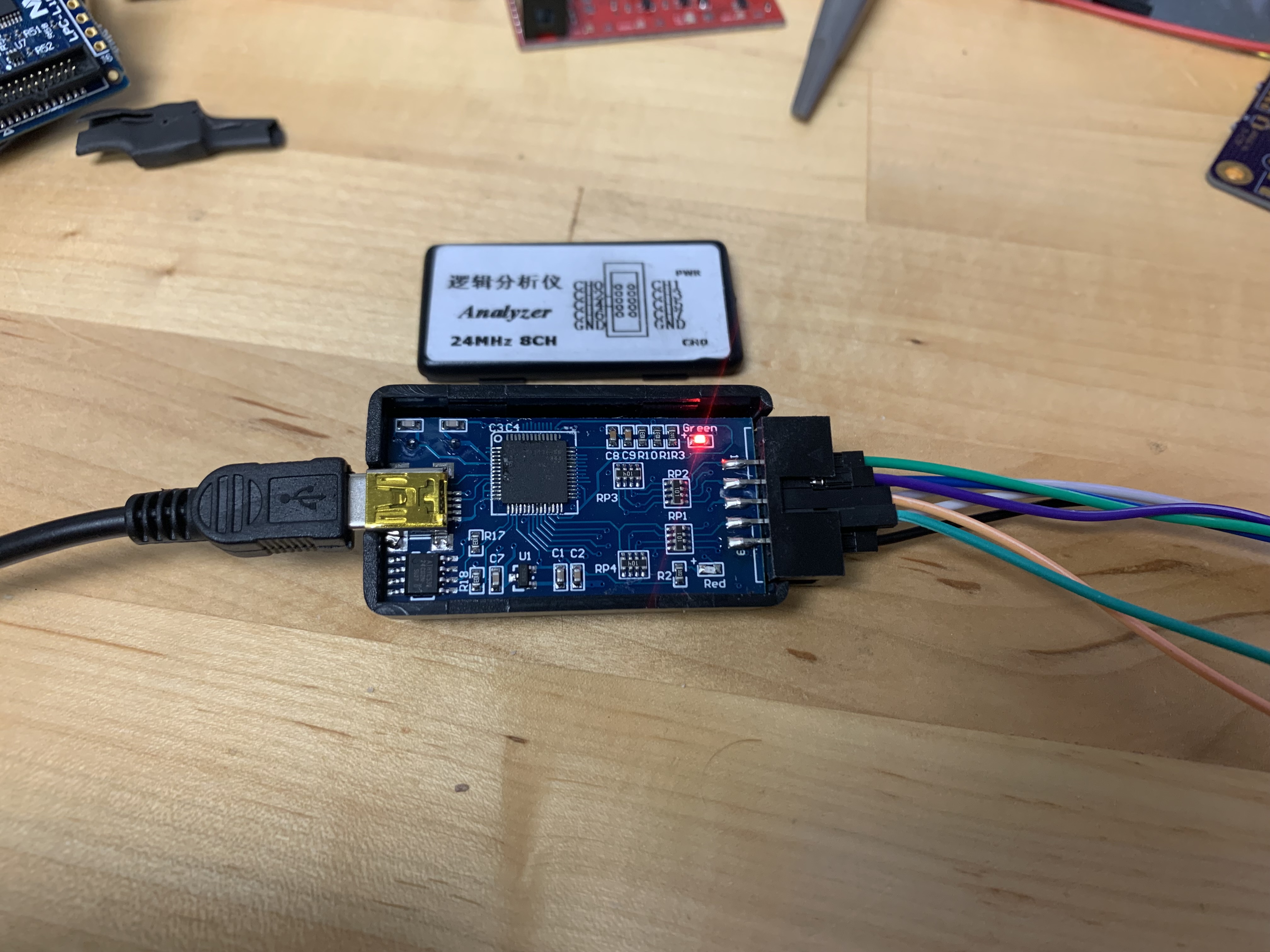
Logic analyzer opened up
Hardware
While I have access to more fancier equipment in the lab, I was looking for a compact, budget-friendly solution to take on the go. This fx2 logic analyzer fits the bill, offering surprisingly good performance and the price is absurd.
My reliable code rubber ducky wasn’t getting the problem solved. I was on the road and away from the lab so I needed something portable.
Enter the basic 48 MHz fx2 logic analyzer. Apparently it’s a Saleae clone but this piece of hardware is incredibly simple, there isn’t any non-volatile storage to store the firmware even. There are some great intro videos from the OpenTechLab (who worked extensively on the open source GUI for the analyzer). His website has a bunch of applications of these things also.
The fx2 based Saleae clones are identical to (although typically value engineered versions of) those torn down by Dave Jones. Sparkfun has a version also which appears to be the same thing as the AliExpress ones although I haven’t done a tear down of them. I bought this one off Amazon, happy to report the label is exactly as crooked as the one in the product image.
Logic analyzer opened up
Software
The logic analyzer has no software on it, that is entirely provided by Sigrok
- Firmware Driver: sigrok-firmware-fx2lafw
- Application / Library: sigrok
- Interface: sigrok-cli, PulseView
The software is trivial to set up on Ubuntu. There are minor bugs but it works. Running two instances at the same time is possible but fraught.
Uses
Sigrok supports a huge set of decoders and hardware. I’ve been using the FTDI + Modbus decoder to great utility in addition to the SPI & I2C from this project.
SPI ADC
- ADC has an IRQ pin when the conversion is completed
- This causes a pin interrupt which starts an SPI conversion
- IRQ pin should go high-Z after the read command has been received.
- I hooked up the signals by soldering wire wrap wire to IC pins to a superglued 0.1" header on the board edge
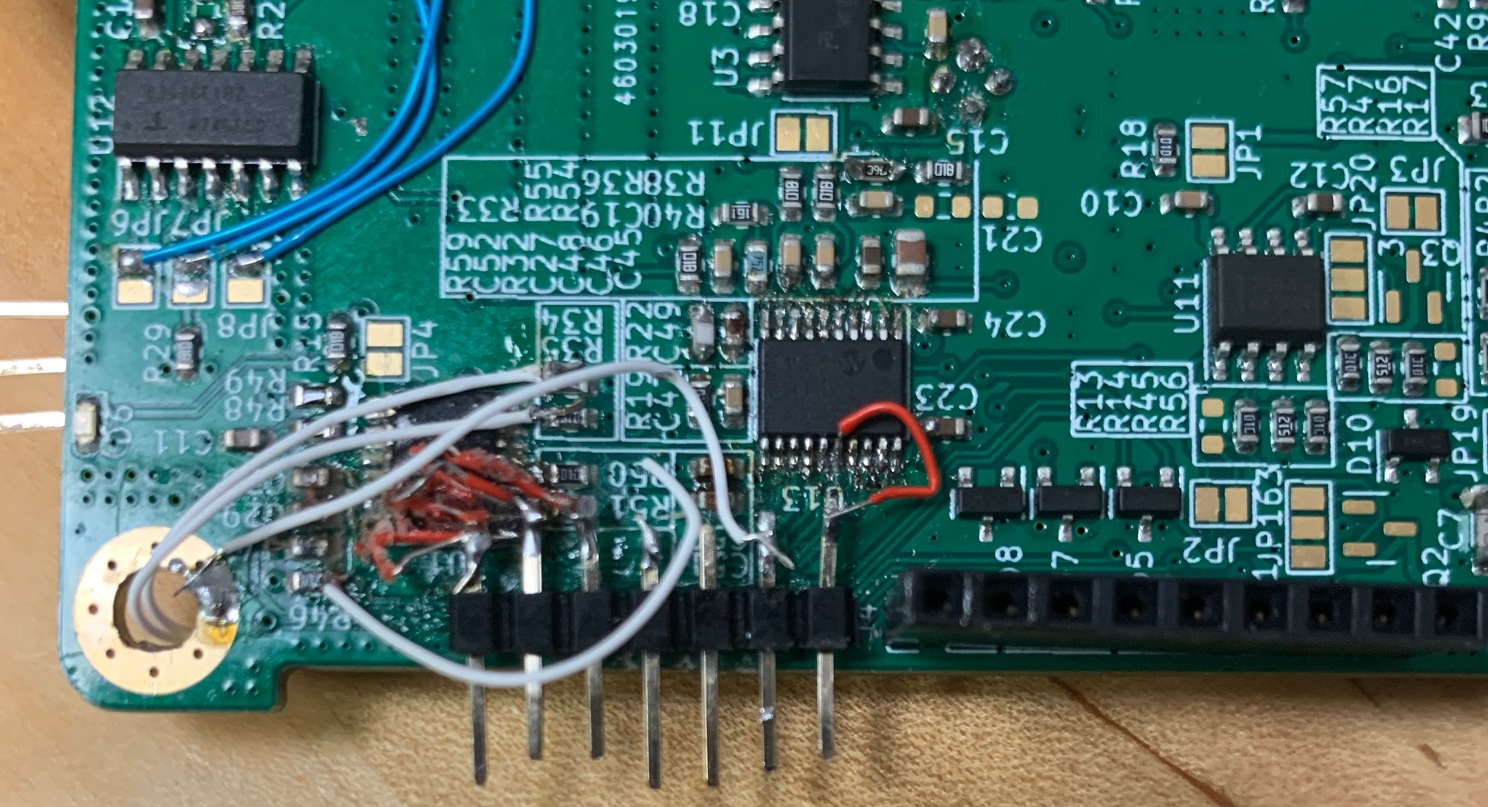
Glued Header
The hookup wire is not pretty but the header is robust and sped up evaluation like crazy. I do wish I had put more test pads on this board.
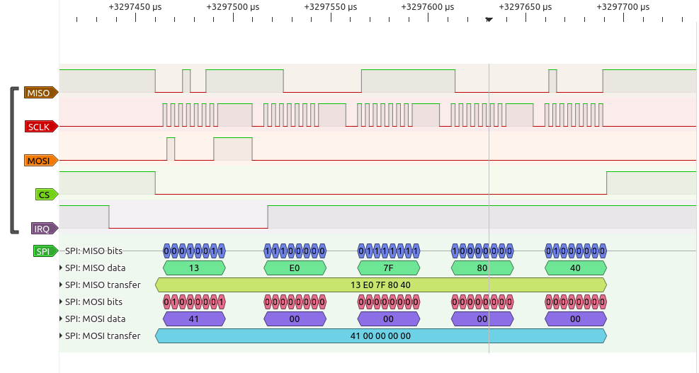
Sigrok SPI Decoding Example
The PulseView output here shows the decoding to hex and I can add the other signals that are related like the IRQ.
The data output can be saved as a session or exported as any number or formats. VCD output is particularly useful as that fits in with typical FPGA simulation formats.
Conclusion
This is a great tool to have available to breakout early in the debug process. With the addition of a few extra headers to the board layout this could be pulled out of your bag and spun up to decrease the debug time and the cognitive load when tackling a bug in hardware+software interaction. Buy 5, put them everywhere.